Symbol For Engineering Drawing
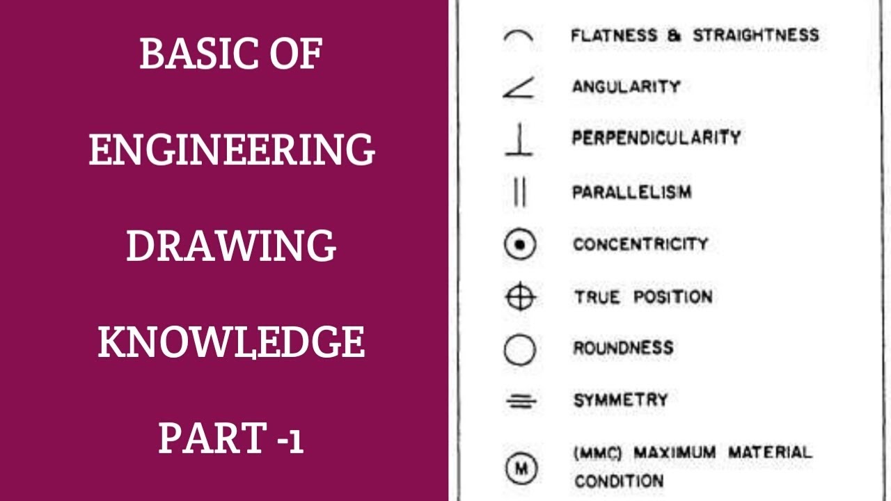
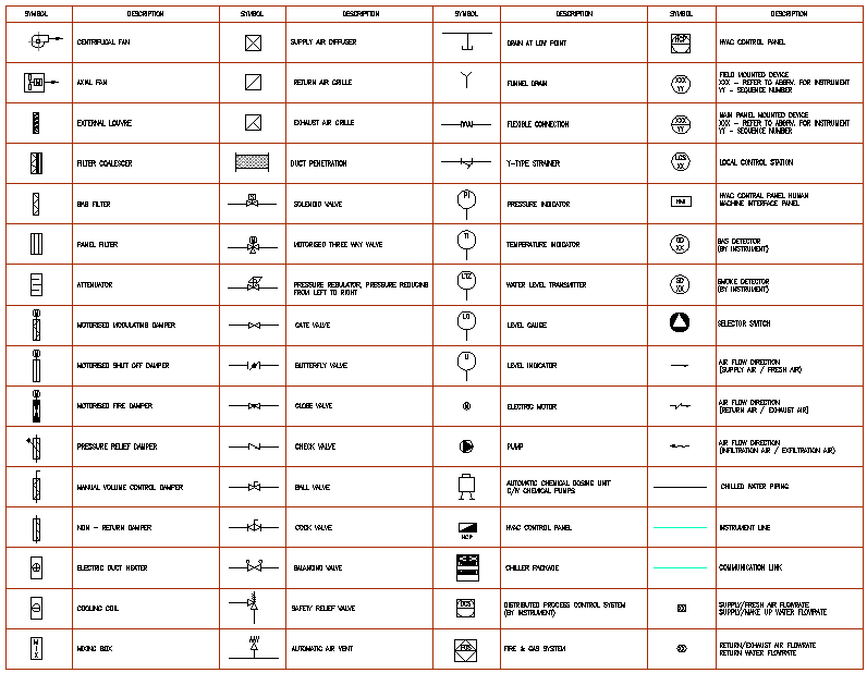
Symbol For Engineering Drawing - Explore asme’s latest editions of the y14 design. Web this chapter covers all of the major gd&t tools for engineering drawings including dimensions, tolerances, gd&t symbols, datums, feature control frames and more Web easy example to understand and interpret engineering drawings. Web 18.06.2020 by andreas velling engineering drawing basics explained an engineering drawing is a subcategory of technical drawings. Currently, we have 16 symbols for geometric tolerances, which are categorized according to the tolerance they. Web the following are definitions commonly used throughout industry when discussing gd&t or composing engineering drawing notes. Web engineering drawings (aka blueprints, prints, drawings, mechanical drawings) are a rich and specific outline that shows all the information and requirements needed to. Web understanding welding symbols in drawing. Many of the definitions are not official asme,. For example, engineering symbols are used in technical drawings to convey. Please like if you would like to. Many of the definitions are not official asme,. For example, engineering symbols are used in technical drawings to convey. Drawings convey the following critical information: Web some commonly used material symbols include: For example, engineering symbols are used in technical drawings to convey. Web graphics communications are used in every phase of engineering design starting from concept illustration all the way to the manufacturing phase. Subscribe and don't miss new videos! Stay in the know with the latest methods, terms, applications, symbols, abbreviations and diagrams. Web understanding welding symbols in drawing. Web 1.6 identify the symbols used on engineering p&ids to denote the location, either local or board mounted, of instruments, indicators, and controllers. Web some commonly used material symbols include: Web a set of standardized p&id symbols is used by process engineers to draft such diagrams. P&id symbols exist for all major components and lines, such as valves,. Drawings convey. Many of the definitions are not official asme,. Explore asme’s latest editions of the y14 design. Web engineering drawings (aka blueprints, prints, drawings, mechanical drawings) are a rich and specific outline that shows all the information and requirements needed to. We notice welding symbols in fabrication & engineering drawings where lines and special geometrical shapes such. Drawings convey the following. How the object will look when it is viewed from various angles, such as front, top, side, etc. Web understanding welding symbols in drawing. Web easy example to understand and interpret engineering drawings. Explore asme’s latest editions of the y14 design. Please like if you would like to. How the object will look when it is viewed from various angles, such as front, top, side, etc. Web there are literally hundreds of engineering drawing symbols and they’re used in a variety of ways. Web engineering drawings (aka blueprints, prints, drawings, mechanical drawings) are a rich and specific outline that shows all the information and requirements needed to. Web. Web the following are definitions commonly used throughout industry when discussing gd&t or composing engineering drawing notes. Web some commonly used material symbols include: Web geometric tolerances are specified using symbols on a drawing. Web graphics communications are used in every phase of engineering design starting from concept illustration all the way to the manufacturing phase. For example, engineering symbols. Please like if you would like to. Drawings convey the following critical information: Web engineering drawings (aka blueprints, prints, drawings, mechanical drawings) are a rich and specific outline that shows all the information and requirements needed to. Web there are literally hundreds of engineering drawing symbols and they’re used in a variety of ways. Web 1.6 identify the symbols used. Web this chapter covers all of the major gd&t tools for engineering drawings including dimensions, tolerances, gd&t symbols, datums, feature control frames and more The purpose is to convey all the. Please like if you would like to. Web there are literally hundreds of engineering drawing symbols and they’re used in a variety of ways. Stay in the know with. Web engineering drawings (aka blueprints, prints, drawings, mechanical drawings) are a rich and specific outline that shows all the information and requirements needed to. For example, engineering symbols are used in technical drawings to convey. Web some commonly used material symbols include: How the object will look when it is viewed from various angles, such as front, top, side, etc.. Web geometric tolerances are specified using symbols on a drawing. Drawings convey the following critical information: The wood symbol is used to represent wooden components or objects in drawings. Web there are literally hundreds of engineering drawing symbols and they’re used in a variety of ways. Many of the definitions are not official asme,. Web this chapter covers all of the major gd&t tools for engineering drawings including dimensions, tolerances, gd&t symbols, datums, feature control frames and more Web some commonly used material symbols include: Subscribe and don't miss new videos! Web understanding welding symbols in drawing. Stay in the know with the latest methods, terms, applications, symbols, abbreviations and diagrams. Web 1.6 identify the symbols used on engineering p&ids to denote the location, either local or board mounted, of instruments, indicators, and controllers. Web graphics communications are used in every phase of engineering design starting from concept illustration all the way to the manufacturing phase. For example, engineering symbols are used in technical drawings to convey. Web engineering drawings (aka blueprints, prints, drawings, mechanical drawings) are a rich and specific outline that shows all the information and requirements needed to. We notice welding symbols in fabrication & engineering drawings where lines and special geometrical shapes such. P&id symbols exist for all major components and lines, such as valves,.
Types of Engineering Drawing Symbols and Uses इंजीनियरिंग ड्राइंग के

Civil Engineering Drawing Symbols And Their Meanings at PaintingValley

How To Read Architectural Drawings Symbols The Architect

Engineering Drawing Symbols And Their Meanings Pdf at PaintingValley

Engineering Drawing Symbols And Their Meanings Pdf at PaintingValley

Engineering Drawing Symbols And Their Meanings Pdf at PaintingValley

Engineering Drawing Symbols And Their Meanings Pdf at PaintingValley

Mechanical Engineering Drawing Symbols Pdf Free Download at

Technical Drawing Symbols

Mechanical Engineering Symbols Cadbull
Web A Set Of Standardized P&Id Symbols Is Used By Process Engineers To Draft Such Diagrams.
Currently, We Have 16 Symbols For Geometric Tolerances, Which Are Categorized According To The Tolerance They.
Web Easy Example To Understand And Interpret Engineering Drawings.
Web 18.06.2020 By Andreas Velling Engineering Drawing Basics Explained An Engineering Drawing Is A Subcategory Of Technical Drawings.
Related Post: