Pipework Drawings
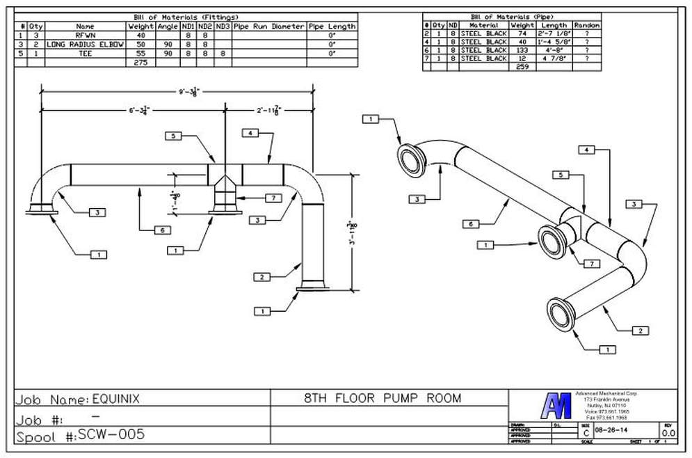
Pipework Drawings - The piping isometrics software can be extended to process data from other 3d cad and plant design systems. The pipe lengths are determined by. Piping isometric drawing consists of three sections. Piping plan drawings/general arrangement drawings (gad). Unlike orthographics, piping isometrics allow the pipe to be drawn in a manner by which the length, width and depth are shown in a single view. Web what are the requirements for a piping drawing? Pipes are shown as single lines, and symbols are used to represent pipe fittings, valves, pipe gradients, and welds. Web how to read piping isometric drawing symbols. Web it is the most important deliverable of any project where piping plays a vital role. By definition, isometrics drawings are a graphic representation of a 3d routed line in a 2d plane that combines height, length of pipe in a single drawing with a 30º angle on both sides from horizontal. Unlike orthographics, piping isometrics allow the pipe to be drawn in a manner by which the length, width and depth are shown in a single view. A primary instrument is an instrument that. When using software, it is. Web we are concluding our first pipefitter series run with a video on how to draw isometric drawings. Second, draw the pipeline. Checkout list of such symbols given below. An integrated autorouting function is also available for rapid pipe positioning. Web fast and simple piping design in 3d. Pipe diameter contents and identification number; Piping fabrication work is based on isometric drawings. Are tagged with the same codes used on the p&id and ga. For designing processes or power piping, mostly five types of piping drawings are developed. A primary instrument is an instrument that. In the chart above, it is necessary to know where the instrument is located and its function in order to draw it correctly on a p&id. Web. Web one person referred to it as “a new russian space threat capability.”. A primary instrument is an instrument that. When using software, it is. Web a piping system drawing may be represented by the following three methods. Web isometric piping drawings are not scale drawings, so they are dimensioned. Checkout list of such symbols given below. Web for example in stream 39 in figure a, the pipe has a 4 diameter, services/carries the chemical denoted 'n', is made of carbon steel, and has no insulation. Web this is a certified workshop! Web create the piping isometric drawing manually 1. Piping fabrication is done as per the below. M4 plant is the perfect software for all areas of piping design. An integrated autorouting function is also available for rapid pipe positioning. Create a drawing sheet for isometrics. When using software, it is. Web this is a certified workshop! To ensure the nozzle elevation and orientation is proper. Create a drawing sheet for isometrics. Second, draw the pipeline with the help of simple lines. Pipes are shown as single lines, and symbols are used to represent pipe fittings, valves, pipe gradients, and welds. Web what are the requirements for a piping drawing? Draw the route of the pipeline. Piping plan drawings/general arrangement drawings (gad). Many abbreviations are common and are regularly used in the drawings. Web isometric drawings are commonly used in industries such as the oil and gas industry, petrochemical industry, and plumbing for planning, design, construction, and pipeline maintenance. By definition, isometrics drawings are a graphic representation of a 3d. It is the most important deliverable of piping engineering department. In the chart above, it is necessary to know where the instrument is located and its function in order to draw it correctly on a p&id. Checkout list of such symbols given below. The piping plan or general arrangement drawings (fig. Web for example in stream 39 in figure a,. Web the pipe fabrication process requires assembling pipes and pipe fittings according to the spool drawing. A primary instrument is an instrument that. Pipe fabricators must take into consideration the size of the assembly, as transportation could be a problem. Web you can see many piping abbreviations in piping drawing or document. Web fast and simple piping design in 3d. First create a drawing sheet in din a4 or a3 and activate the isometric grid. Second, draw the pipeline with the help of simple lines. When using software, it is. The drawing sheet sizes shall be any of the following. Size and type of valves and fittings; Web how to read piping isometric drawing symbols. Piping layouts will provide information on the pipe route, dimension, elevation, valve orientation, and coordinates. Piping plan drawings/general arrangement drawings (gad). Are tagged with the same codes used on the p&id and ga. Web we are concluding our first pipefitter series run with a video on how to draw isometric drawings. Web this is a certified workshop! Piping fabrication work is based on isometric drawings. Web types of piping drawings (pdf) types of piping drawings. An integrated autorouting function is also available for rapid pipe positioning. Piping isometric drawing consists of three sections. The instructor explains the state of art in.
Sample isometric drawing for piping klowebcam

How to read isometric drawing piping dadver

Isometric Piping Drawings Advenser

PIPING DRAWINGS

How to read piping isometric drawing, Pipe fitter training, Watch the

Pipes Drawing at GetDrawings Free download

Piping isometric drawing examples mazorama

Pipework Sample 2 Quickdraw Mechanical Services

Pipe Sketch at Explore collection of Pipe Sketch

How to Draw Isometric Pipe Drawings in Autocad Gautier Camonect
The Symbols That Represent Fittings, Valves And Flanges Are Modified To Adapt To The Isometric Grid.
Web Piping Isometric Drawing Is An Isometric Representation Of Single Pipe Line In A Plant.
To Ensure The Nozzle Elevation And Orientation Is Proper.
Pipes Are Shown As Single Lines, And Symbols Are Used To Represent Pipe Fittings, Valves, Pipe Gradients, And Welds.
Related Post: