Loop Drawing
Loop Drawing - Web looping is a valuable technique in flowcharting as well as computer programming to repeat a certain course of actions for certain times as instructed by the conditions. Web p&ids and loop diagrams are construction and documentation drawings that depict the flow of the process and illustrate the instrumentation control and measurement. Loop diagrams are composed of wiring details of field instruments engineering costs can be reduced loop integrity is improved the faulty. Web i use a pencil and a sharpie to draw an optical illusion.facebook: Web instrument loop diagram represents detailed drawing showing a connection from one point to control system. Loop diagram shows instrument (in a symbol) and its. Web the different types of instrumentation diagrams which are commonly used are (i) process flow diagram (pfd), (ii) loop diagrams (loop sheets), (iii) process and. Each loop diagram gives you a more detailed view of loop in a process system. The loop diagram is the document consist of all connections of instruments from the field to the control panel. Here we see that the p&id didn’t show us all the instruments in this control. Web this standard establishes minimum required information and identifies additional optional information for a loop diagram for an individual instrumentation loop. Web instrument loop diagram basics. Loop diagram shows instrument (in a symbol) and its. Web loop drawing are mostly drawn on drafting software like autocad but nowadays they can be generated automatically by intelligent design data base softwares. We. Web instrument loop diagram basics. Web what is the purpose of the loop diagram? Each loop diagram gives you a more detailed view of loop in a process system. Web loop diagrams explained. Web i am not talking about making a diagram and adding it like a picture. Web p&ids and loop diagrams are construction and documentation drawings that depict the flow of the process and illustrate the instrumentation control and measurement. Here we are discussing for the compressor surge control system (loop number 42): Web loop drawing are mostly drawn on drafting software like autocad but nowadays they can be generated automatically by intelligent design data base. Web p&ids and loop diagrams are construction and documentation drawings that depict the flow of the process and illustrate the instrumentation control and measurement. Web i am not talking about making a diagram and adding it like a picture. Web loop drawings' content is driven by the client maintenance person who is using it. Loop diagram shows instrument (in a. Web i use a pencil and a sharpie to draw an optical illusion.facebook: Web loop drawing are mostly drawn on drafting software like autocad but nowadays they can be generated automatically by intelligent design data base softwares. Each loop diagram gives you a more detailed view of loop in a process system. We would like to try out loop for. Web loop drawing are mostly drawn on drafting software like autocad but nowadays they can be generated automatically by intelligent design data base softwares. Web converting instrument loop diagrams to cad. Here we are discussing for the compressor surge control system (loop number 42): Web loop drawings' content is driven by the client maintenance person who is using it. Web. In this lesson we go over the ever important and go to document as an instrument technician and that is the loop diagram. Web instrument loop diagram represents detailed drawing showing a connection from one point to control system. Web p&ids and loop diagrams are construction and documentation drawings that depict the flow of the process and illustrate the instrumentation. Web loop drawings' content is driven by the client maintenance person who is using it. Web instrument loop diagram represents detailed drawing showing a connection from one point to control system. In this lesson we go over the ever important and go to document as an instrument technician and that is the loop diagram. Here we are discussing for the. Web a loop diagram will detail the connections and pneumatics and wiring from the field device through any junction boxes or marshalling cabinet to the controller or. Web loop diagrams can be used in conjunction with p and iids. Here we see that the p&id didn’t show us all the instruments in this control. Web i use a pencil and. In most cases, it could be too simple as the diagnostics tool, and one does not. Web loop drawings' content is driven by the client maintenance person who is using it. Web this standard establishes minimum required information and identifies additional optional information for a loop diagram for an individual instrumentation loop. Web i use a pencil and a sharpie. Web this standard establishes minimum required information and identifies additional optional information for a loop diagram for an individual instrumentation loop. We would like to try out loop for our company but we really miss the lack of creating. In most cases, it could be too simple as the diagnostics tool, and one does not. Here’s how you can convert instrument loop diagrams (ilds) to cad using scan2cad. Web instrument loop diagram represents detailed drawing showing a connection from one point to control system. Each loop diagram gives you a more detailed view of loop in a process system. Web loop diagrams can be used in conjunction with p and iids. Web instrument loop diagram basics. Here we see that the p&id didn’t show us all the instruments in this control. Web what is the purpose of the loop diagram? Web loop diagrams explained. Web the different types of instrumentation diagrams which are commonly used are (i) process flow diagram (pfd), (ii) loop diagrams (loop sheets), (iii) process and. Web looping is a valuable technique in flowcharting as well as computer programming to repeat a certain course of actions for certain times as instructed by the conditions. Loop diagram shows instrument (in a symbol) and its. Web loop drawings' content is driven by the client maintenance person who is using it. Web i am not talking about making a diagram and adding it like a picture.
Free Motion Quilting The Ultimate StartUp Guide
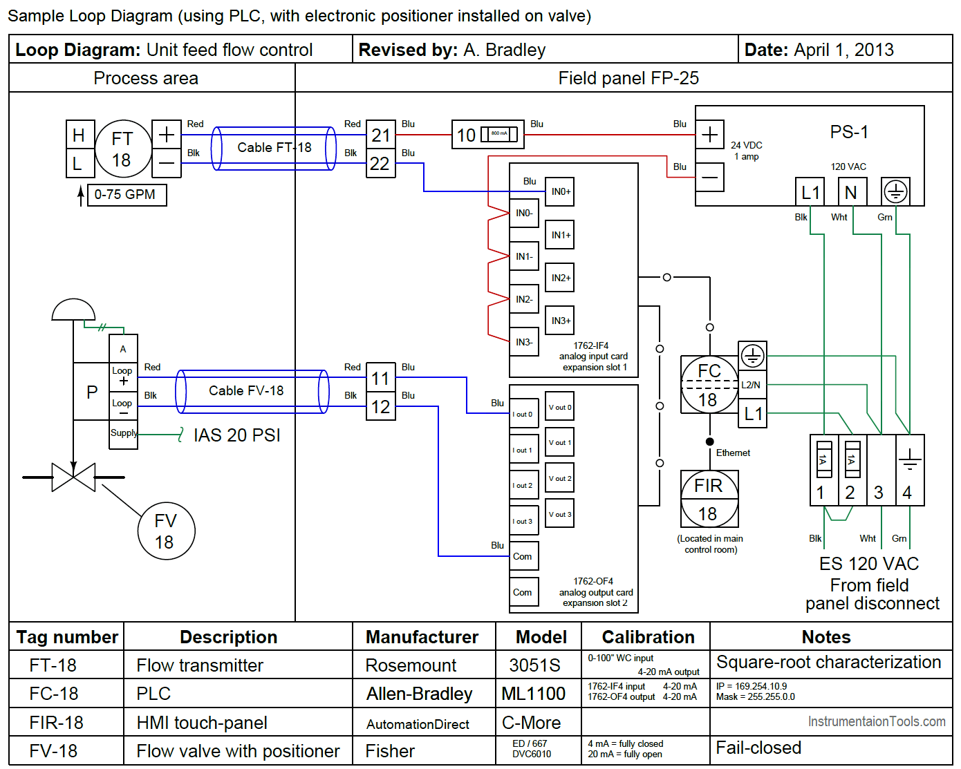
Instrumentation Loop Diagrams InstrumentationTools
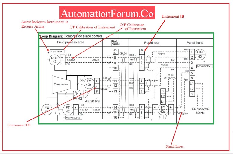
Howto Create Instrument Loop Diagram (ILD)? AutomationForum
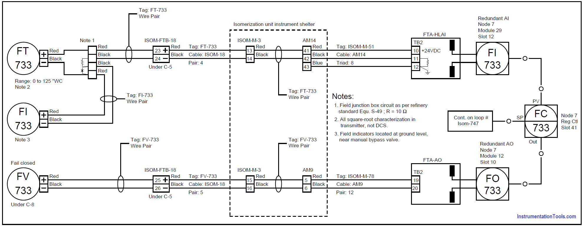
15 Loop Diagram Questions Instrumentation Tools

What is a Loop Diagram Instrumentation Course Lesson 3 YouTube
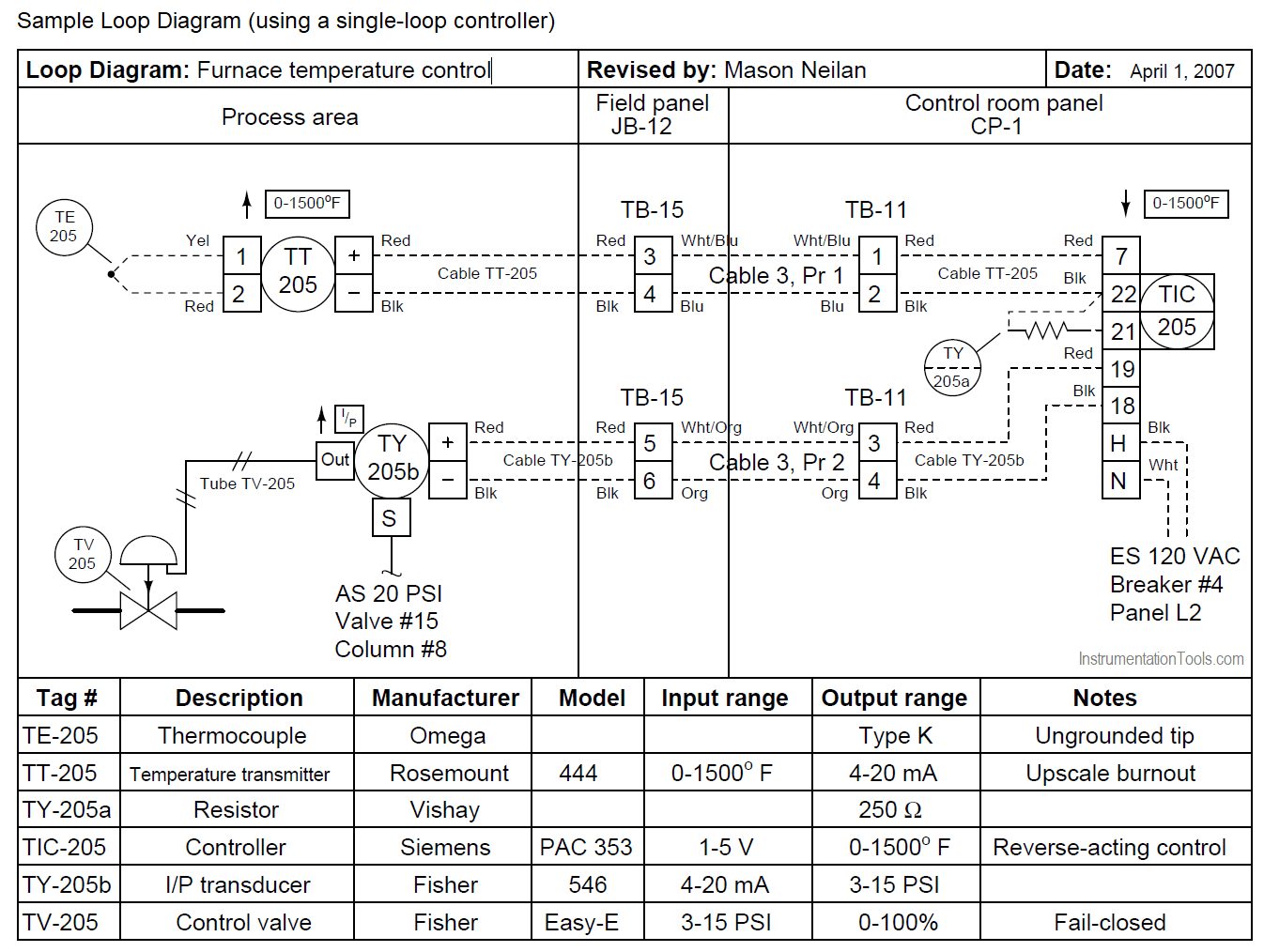
Instrumentation Loop Diagrams InstrumentationTools
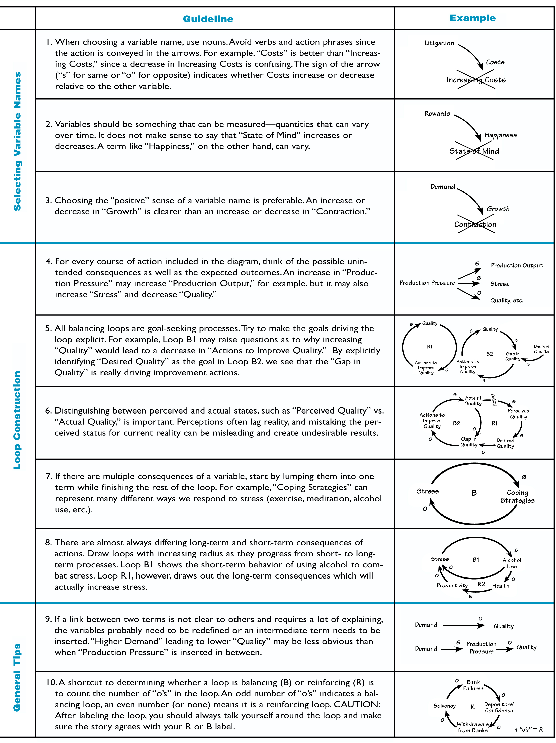
The Systems Thinker Guidelines for Drawing Causal Loop Diagrams The

An infinite loop drawing EASY HOW TO DRAW YouTube

Loop Drawings, 2012 ← Editions ← The Wrong Shop Drawings, Graphic

c How to draw a loop shape in WPF? Stack Overflow
Loop Diagrams Are Composed Of Wiring Details Of Field Instruments Engineering Costs Can Be Reduced Loop Integrity Is Improved The Faulty.
Web A Loop Diagram Will Detail The Connections And Pneumatics And Wiring From The Field Device Through Any Junction Boxes Or Marshalling Cabinet To The Controller Or.
Web Converting Instrument Loop Diagrams To Cad.
In This Lesson We Go Over The Ever Important And Go To Document As An Instrument Technician And That Is The Loop Diagram.
Related Post: