Drawing Symbols Engineering
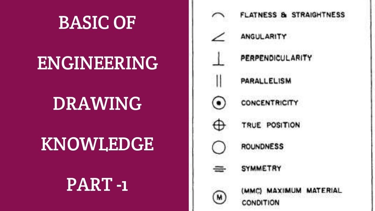
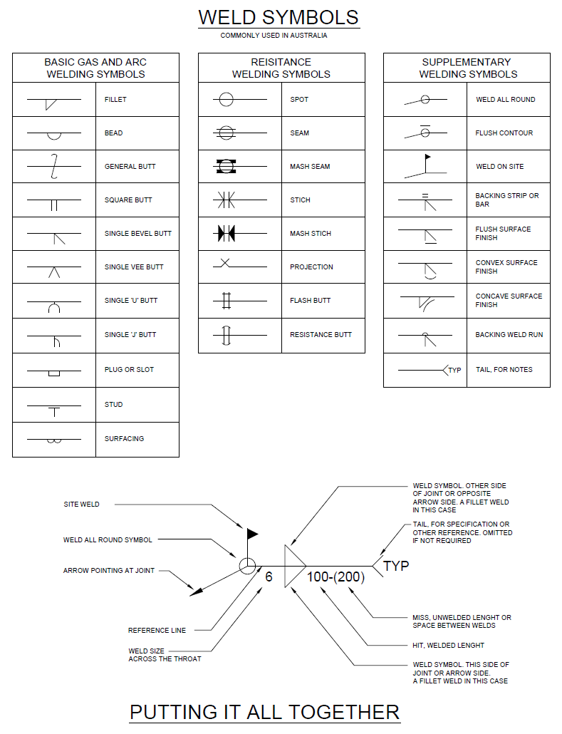
Drawing Symbols Engineering - Web an engineering (or technical) drawing is a graphical representation of a part, assembly, system, or structure and it can be produced using freehand, mechanical tools, or computer methods. Note the comparison with the iso standards. The basic symbol types used in engineering drawings are diameter, depth, radius, counterbore, spotface, and countersink. Web easy example to understand and interpret engineering drawings. We have over 5 years of experience in the drilling space with a strong track record of. This makes understanding the drawings simple with little to no personal interpretation possibilities. Currently, we have 16 symbols for geometric tolerances, which are categorized according to the tolerance they specify. Usually, a number of drawings are necessary to completely specify even a simple component. True position theory (size value in rectangular frame) classification and symbols of geometric tolerance characteristics Web an engineering drawing is a subcategory of technical drawings. Usually, a number of drawings are necessary to completely specify even a simple component. 646 likes · 15 talking about this · 7 were here. Unlike a model, engineering drawings offer more specific detail and requirements, such as: Here are more commonly used engineering drawing symbols and design elements as below. Web an engineering drawing is a subcategory of technical. Web category symbolism engineering drawing symbols are like a secret language that only engineers can decode. Built a 15,000 square feet steel fabrication facility, and began providing fabricated steel items to serve its own customer base. Web easy example to understand and interpret engineering drawings. True position theory (size value in rectangular frame) classification and symbols of geometric tolerance characteristics. These symbols carry specific meanings and convey vital information about various facets of a design. Web an engineering (or technical) drawing is a graphical representation of a part, assembly, system, or structure and it can be produced using freehand, mechanical tools, or computer methods. Engineering drawings use standardised language and symbols. They contain all the information needed to This makes. Web engineering drawings (aka blueprints, prints, drawings, mechanical drawings) are a rich and specific outline that shows all the information and requirements needed to manufacture an item or product. Web segaworx, is a directional and horizontal drilling company. This makes understanding the drawings simple with little to no personal interpretation possibilities. The following are commonly used engineering drawing symbols and. Web bent creek design company, cissna park, illinois. Piston (hydraulic) valve operator e. Hand (manual) valve operator f. True position theory (size value in rectangular frame) classification and symbols of geometric tolerance characteristics Please like if you would like to see more related topics! The basic symbol types used in engineering drawings are diameter, depth, radius, counterbore, spotface, and countersink. Most symbols have been in y14.5 since at least 1994. Web geometric tolerances are specified using symbols on a drawing. They contain all the information needed to Please like if you would like to see more related topics! We are based in bentonville, arkansas and serve the central part of the county primarily arkansas, missouri, illinois, indiana, tennessee, ohio, kentucky. Web segaworx, is a directional and horizontal drilling company. The following are commonly used engineering drawing symbols and design elements. Web basic types of symbols used in engineering drawings are countersink, counterbore, spotface, depth, radius, and diameter. Here. Web geometric tolerances are specified using symbols on a drawing. Web how to read an engineering drawing symbol. Web engineering drawing standards manual. Web since 1986, hoffmann has been providing industrial steel stacks, which was a natural fit into the steel fabrication marketplace. Here are more commonly used engineering drawing symbols and design elements as below. They contain all the information needed to We have over 5 years of experience in the drilling space with a strong track record of. We make personalized products on a wide variety of items including custom apparel, vinyl sign, and v Web igse is a locally based grain and seed company. Web easy example to understand and interpret engineering drawings. Web an engineering (or technical) drawing is a graphical representation of a part, assembly, system, or structure and it can be produced using freehand, mechanical tools, or computer methods. Web engineering drawings (aka blueprints, prints, drawings, mechanical drawings) are a rich and specific outline that shows all the information and requirements needed to manufacture an item or product. Web geometric. A common use is to specify the geometry necessary for the construction of a component and is called a detail drawing. Web engineering drawings (aka blueprints, prints, drawings, mechanical drawings) are a rich and specific outline that shows all the information and requirements needed to manufacture an item or product. Subscribe and don't miss new videos! Web engineering drawing standards manual. Unlike a model, engineering drawings offer more specific detail and requirements, such as: We specialize in making darn good holes. Here are more commonly used engineering drawing symbols and design elements as below. Currently, we have 16 symbols for geometric tolerances, which are categorized according to the tolerance they specify. It is more than simply a drawing, it is a graphical language that communicates ideas and information. Working drawings are the set of technical drawings used during the manufacturing phase of a product. Please like if you would like to see more related topics! Engineering drawings use standardised language and symbols. Web geometric tolerances are specified using symbols on a drawing. Built a 15,000 square feet steel fabrication facility, and began providing fabricated steel items to serve its own customer base. Web basic types of symbols used in engineering drawings are countersink, counterbore, spotface, depth, radius, and diameter. Web 1.2 identify the symbols used on engineering p&ids for the following types of valve operators:
Engineering Drawing Symbols And Their Meanings Pdf at PaintingValley

Engineering Drawing Symbols And Their Meanings Pdf at PaintingValley

Civil Engineering Symbols ( Engineering Drawing) YouTube

Mechanical Engineering Drawing Symbols Pdf Free Download at
M&e Drawing Symbols Back To Basics Komseq

Engineering Drawing Symbols And Their Meanings Pdf at PaintingValley

Engineering Drawing Symbols And Their Meanings Pdf at PaintingValley

Civil Engineering Drawing Symbols And Their Meanings at PaintingValley

Civil Engineering Drawing Symbols And Their Meanings at PaintingValley

Mechanical Engineering Drawing Symbols Pdf Free Download at
We Have Over 5 Years Of Experience In The Drilling Space With A Strong Track Record Of.
Stay In The Know With The Latest Methods, Terms, Applications, Symbols, Abbreviations And Diagrams.
The Basic Symbol Types Used In Engineering Drawings Are Diameter, Depth, Radius, Counterbore, Spotface, And Countersink.
We Make Personalized Products On A Wide Variety Of Items Including Custom Apparel, Vinyl Sign, And V
Related Post: